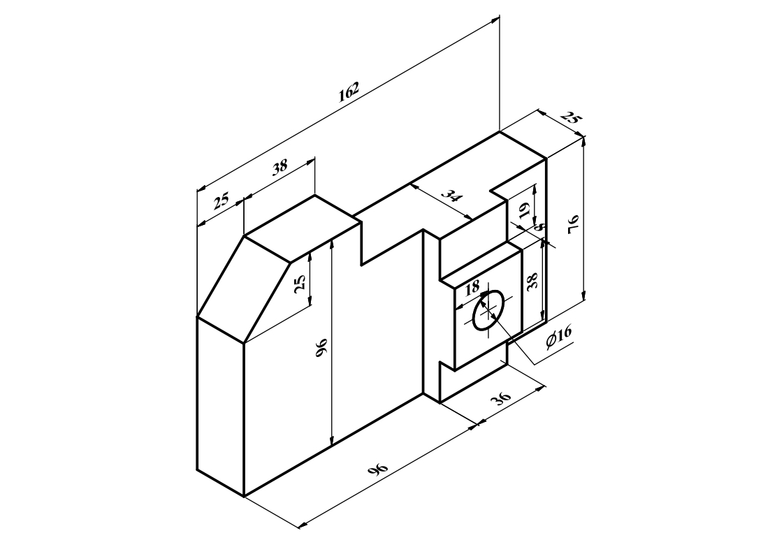
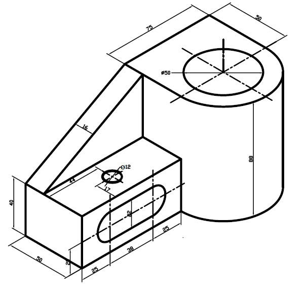
Inventor 2D and 3D drawings and video tutorials are shown below. You can see many different 3D CAD programs drawings here. If you want to practice Inventor drawings, try sharing technical drawings. Also you can use it different CAD programs.
Watch video to see how this part is created in Inventor.
Follow my channel to see different CAD practice videos and drawings. If you subscribe my channel, you don't miss new CAD tutorials and drawings.
I create many different technical drawings in Inventor, Catia and FreeCAD. If you have an interest for CAD programs, I recommend to follow my youtube channel.
Part is created by mirror command. Firstly half of part is created on part design and 2D sketch, then mirror command is used to reflect other half. We can use mirrored to create symmetric drawings as a short way.
Technical drawing is below that used in video tutorial.
Part Design Mirrored command creates a new object (image) which is a reflection of the original object (source). The image object is created behind a mirror plane. The mirror plane may be standard plane (XY, YZ, or XZ), or any plane parallel to a standard plane.
If you want, you can change planes or direction according to technical drawing or your preference. To use it, just follow simple steps below.
Select the object from the Mirroring Panel list.
Select a standard Mirror plane from the dropdown menu.
Press OK to create mirrored object.
When you watch video tutorial below, You will see how to create part above and mirror in freecad.
Freecad is an open source CAD program to create your own designs or drawing in 2D or 3D environment. You can download it, if you want to try. I have different video tutorials to learn how to use freecad.
This technical drawing can be used in CAD programs to practice.
FreeCAD part design tutorials will continue and you can see here more technical drawing with detail explanations. If you subscribe my youtube channel, Tutorials can be seen easily.
This is 20th part design tutorial of technical drawing.
All dimensions are clear to create this part design which is shown in technical drawing. When you watch video tutorial, you will see all details of contraints.
Tutorial contains
How to create construction circle in freecad
How to create tangent constrain, coincident constraint and point constraint
Creating construction line with angel constrain
Pad and pocket tutorial for beginners
Creating a rib in freecad
How to create polar pattern in freecad or Circular pattern
Fillet with changing radius
How to use refine in freecad for part design drawings
FreeCAD Part Design Video Tutorial Technical drawing is below..Video contains how to design this part in FreeCAD workbench. If you want to practice, you can watch all steps in video then you can create same drawing.
Drawing contains
How to decide starting plane in 2D sketch
Creating plane according to technical drawing
Using 2D sketch constraints relations
Creating constraints
Using Isometric View to create a sketch.
Adding Dimensions
Creating sketch without external geometry
Creating pad and pocket in symmetric to plane.
How to use symmetry button in FreeCAD 2D sketch
How to refine parts
VIDEO TUTORIAL OF THIS PART
If you want see all these steps, I recommend to watch below video. Subscribe my youtube channel to see more CAD tutorials. I share tutorial videos regularly.
FreeCAD Part Design Video Tutorial Technical drawing is below. This time, I create front and top view in drawing.Video contains how to design this part in FreeCAD workbench. If you want to practice, you can watch all steps in video then you can create same drawing.
Drawing contains
How to decide starting plane in 2D sketch
Creating plane according to technical drawing
Using 2D sketch constraints relations
Creating constraints
Using Isometric View to create a sketch.
Adding Dimensions
Using lock constraint
Creating sketch without external geometry
Creating pad and pocket in symmetric to plane.
How to use symmetry button in FreeCAD 2D sketch
Linear Pattern in 3D sketches
If you want see all these steps, I recommend to watch below video. Subscribe my youtube channel to see more CAD tutorials. I share tutorial videos regularly.
This technical drawing is created for CAD programs like Catia, Solidworks, FreeCAD, Inventor etc. You can practice for education.
To create this part in FreeCAD, Mirror,copy,symmetry,construction geometry and lock constraint commands in 2D sketch. Then pad,fillet and pocket command in 3D part design workbench.
This tutorial is created for beginners. Not only FreeCAD but also other CAD program users can create easily,when you watch tutorial video.
If you want to watch video how to create this part, You can watch video below.
Assembly 4 Video tutorial helps to understand how to create LCS of parts and how to attach assembly parts in FreeCAD Assembly 4 workbench.
When you watch video, you can follow assembly notes here. This will be useful to create and select parts easily. You should follow order of assembly parts like in video .
After opening assembly parts and creating LCS coordinates, You will follow these steps.
I start with first part which is base. You don't need to create any LCS. Base part is fixed, so fixed parts inserted directly without coordinates. You need to just click parent assembly.
Second part is Bush. This time LCS coordinates are selected like below picture. Click hole axis both side in list. After that click 2 times rotate y axis button to obtain right position of bush part.
You need to do same things for second bush. Part is same, so assembly process is not different. You just click hole axis for base and bush.
Third part is Pivot. It has only one LCS which is hole axis. Firstly click hole axis than click LCS bush face. After that click 2 times "rotate Y axis" button then click 3 times "rotate Z axis " button to complete pivot assembly.
Fourth part is washer. It also has one LCS. It attaches to "Base" part. Click LCS washer for attached part like in picture.
Fifth part is bolt. After inserting it, you need to click LCS bolt and washer to complete assembly of bolt part. Just click LCS bolt and LCS washer like below picture. After that enter 2mm thicknes in Z direction.
Last part is nut. It has one LCS to attached base part. Click LCS nut in assembly list. You don't need to rotate or enter dimension.
If you watch video below, You will understand better how Assembly 4 works in FreeCAD.
FreeCAD Part Design Video Tutorial Technical drawing is below. This time, I create front and top view in drawing.Video contains how to design this part in FreeCAD workbench. If you want to practice, you can watch all steps in video then you can create same drawing.
Both technical drawings use for same part design tutorial. First one is for how to decide starting plane. Thats why views have no dimensions. Both view can be used according to part.
Drawing contains
How to decide starting plane in 2D sketch
Creating datum plane according to technical drawing
Using 2D sketch constraints relations
Creating constraints
Using Isometric View to create a sketch.
Adding Dimensions
Using lock constraint
Creating sketch without external geometry
Creating pad and pocket in symmetric to plane.
How to use symmetry button in FreeCAD 2D sketch
Mirror tool in 2D and 3D sketches
How to copy in FreeCAD
Cloning in FreeCAD 2D sketch
Creating Rib and Support part in FreeCAD
If you want see all these steps, I recommend to watch below video. Subscribe my youtube channel to see more CAD tutorials. I share tutorial videos regularly.
FreeCAD Part Design Video Tutorial Technical drawing is below. This time, I create two drawings with views.Video contains how to design this part in FreeCAD workbench. If you want to practice, you can watch all steps in video then you can create same drawing.
Both technical drawings use for same part design tutorial. First one is for how to decide starting plane. Thats why views have no dimensions.
Drawing contains
How to decide starting plane in 2D sketch
Creating datum plane according to technical drawing
Using 2D sketch constraints relations
Adding constraints
Using Isometric View to create a sketch.
Adding Dimensions
Using lock constraint
Creating sketch without external geometry
Creating pad and pocket in symmetric to plane.
When you watch below video, You will see how to do these in FreeCAD
Constraint Lock applies Horizontal distance and Vertical distance constraints to selected vertices (points) in the sketch. If a single vertex is selected, the horizontal and vertical distance constraints will refer to the sketch origin point. If two or more points are selected, horizontal and vertical distance constraints will be added for each pair of points.
It provides easiness which helps to create desired constraints in 2D sketch. Lock constraint button is located on top sides of constraints set.
This is the picture of lock constraint
TECHNICAL DRAWING OF VIDEO TUTORIAL
How to use lock constraint ? Read these 3 steps to use it.
1- Select one or more vertices (points) in the sketch.
2-Press the Sketcher Constrain lock button.
3-To edit the constraints values, double-click on a constraint value in the 3D view, or double-click on the constraint or right-click and select Edit value in the Constraint list in the Tasks tab.
This is technical drawing is created by using lock constraint button.
FreeCAD Part Design Video Tutorial Technical drawing is below. Video contains how to design this part in FreeCAD workbench. If you want to practice, you can watch all steps in video then you can create same drawing.
Drawing contains
Adding plane
Creating rib
Using 2D sketch constraints relations
Adding constraints
Using Isometric View to create a sketch.
Adding Dimensions
Creating plane
Creating Chamfers
Hide and show datum plane in FreeCAD
Creating pad and pocket in symmetric to plane.
When you watch video below, You will see how to do these in FreeCAD
This is tenth part design tutorial. If you want to watch other freecad tutorials, Follow my channel. I share freecad tutorials regularly.
FreeCAD is one of the open source CAD software. That's why it can have a update. If you want to use or try latest version. Check freecad official website. I use 0.20 version of FreeCAD. Follow FreeCAD website to download latest version.
FreeCAD part design tutorial technical drawing is below. This is the ninth part design tutorial and tutorials will continue. If you want to watch tutorial or practice with this part, I recommend to you follow my channel. You will see all steps of tutorial.
Drawing Includes;
Selecting 2D plane to start a drawing( which plane should be selected? xy,yz or xz planes)
Using a isometric view.
Creating constraints in 2d workbench
Drawing Centered rectangle
Changing dimension in FreeCAD( 2d -3d)
Adding Dimensions in 2d environment
Creating pad and selecting faces to draw 2d sketch
Understanding which plane is used in FreeCAD
Ninth part design helps to understand these list. I share a video here. You can watch my video and see technical drawing above. I recommend to watch video. I tell you how to draw it.
TUTORIAL VIDEO IS HERE
If you subscribe and follow my channel. You can watch different freecad tutorials. I share videos regularly on my youtube channel.
FreeCAD part design technical drawing is below. It can be used for CAD programs for practice. You can improve your CAD skills. I add different FreeCAD tutorials.
Part Design 8 Technical Drawing
Video Tutorial is below
I have also freecad assembly, technical drawing and 2D sketch videos. Don't forget to subscribe my channel to see more FreeCAD contents.
FreeCAD is an open source program. Its free, this means you don't need to pay money for this program. Just download from freecad website and set up.
FreeCAD part design tutorial technical drawing is below. This is the 6th part design tutorial and tutorials will continue. If you want to watch tutorial or practice with this part, I recommend to you follow my channel. You will see all steps of tutorial.
Drawing Includes;
Selecting 2D plane to start a drawing( which plane should be selected? xy,yz or xz planes)
Using a isometric view.
Creating constraints in 2d workbench
Changing dimension in FreeCAD( 2d -3d)
Adding Dimensions in 2d environment
Creating pad and selecting faces to draw 2d sketch
Understanding which plane is used in FreeCAD
6th part design helps to understand these list. I share a video here. You can watch my video and see technical drawing above. I recommend to watch video. I tell you how to draw it.
FreeCAD Part Design Video Tutorial Technical drawing is below. Video contains how to design this part in FreeCAD workbench. If you want to practice, you can watch all steps in video then you can create same drawing.
Drawing contains
Adding plane
Creating rib
Using mirror command
Adding constraints
Adding Dimensions
Creating Chamfers
Hide and show planes in FreeCAD
Creating pad and pocket in symmetric to plane.
When you watch video below, You will see how to do these in FreeCAD.
This is 5th part design tutorial. If you want to watch other freecad tutorials, Follow my channel. I share freecad tutorials regularly.
FreeCAD is one of the open source CAD software. That's why it can have a update. If you want to use or try latest version. Check freecad official website.
Video contains adding constraints, how to enter dimension, how to mirror in part design,how to create filled in sketch and how to change color of part.
Video Tutorial is Technical Drawing
This tutorial is for beginners. If you want to see more freecad tutorials, you can follow my channel. I make a frecad videos regularly. Also you can practice with technical drawings.
Freecad release new version is 0.20. Visit freecad website and download latest version.
FreeCAD Part Design tutorial is shown youtube with all details in youtube video. Technical drawing is attached here and below video.
You can look here to practice with video.
If you want to see different FreeCAD videos, you can subscribe my youtube channel. You can watch many CAD video tutorials. I add technical drawings of tutorial. You can use it any CAD programs
Video contains pad, circular pattern, 2d mirror, construction line and pocket commands. You can see all steps with explanations
Part Design Video Tutorial of this technical drawing below.
I will continue with other part design and FreeCAD tutuorial. All drawing and video tutorial will be shared on this blog.
New version of FreeCAD is released. I advise to you download it. New features are added. Also many bugs and errors are fixed.
FreeCAD is an open source CAD program. Open source programs can have bugs, so FreeCAD always have updates. You should check FreeCAD website to follow new versions.