9 Mart 2023 Perşembe

FreeCAD Part Design Tutorial 13

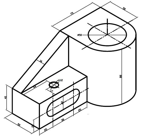
  FreeCAD Part Design Video Tutorial Technical drawing is below. This time, I create two drawings with views.Video contains how to design this part in FreeCAD workbench. If you want to practice, you can watch all steps in video then you can create same drawing.

 Both technical drawings use for same part design tutorial. First one is for how to decide starting plane. Thats why views have no dimensions.

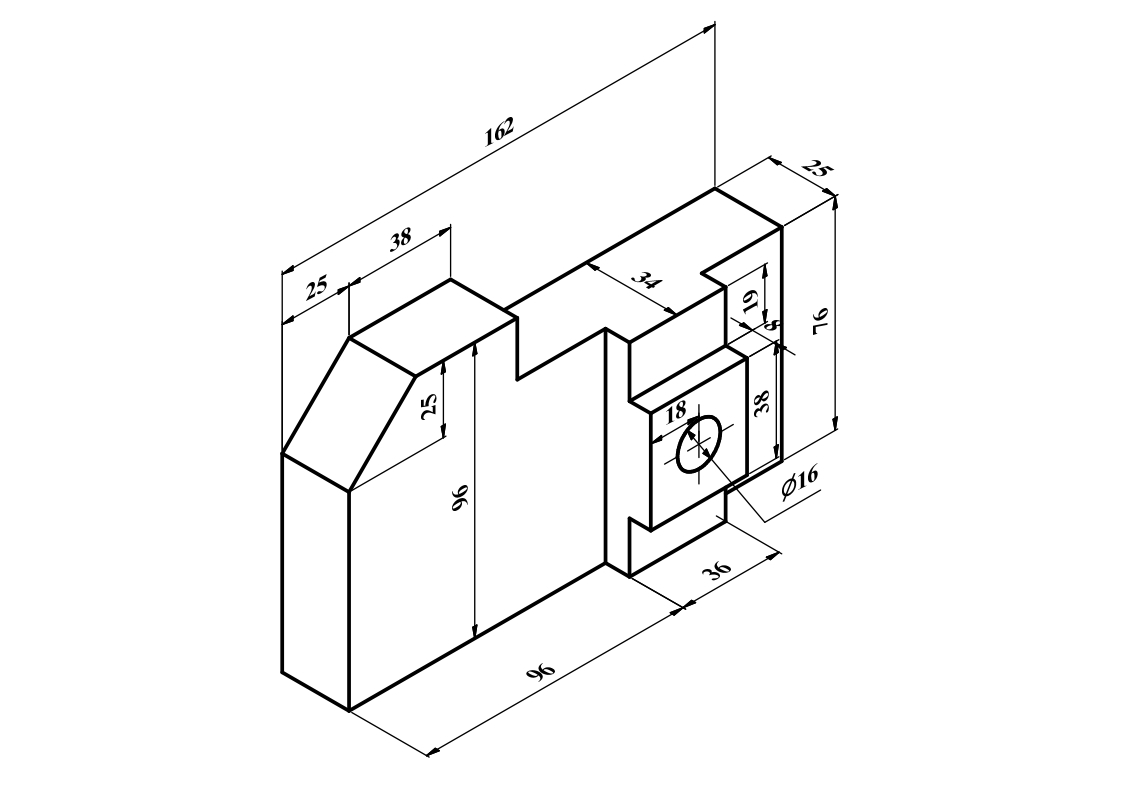
 Drawing contains

  • How to decide starting plane in 2D sketch
  • Creating datum plane according to technical drawing
  • Using 2D sketch constraints relations
  • Adding constraints
  • Using Isometric View to create a sketch.
  • Adding Dimensions
  • Using lock constraint
  • Creating sketch without external geometry
  • Creating pad and pocket in symmetric to plane.
When you watch below video, You will see how to do these in FreeCAD


5 Mart 2023 Pazar

FreeCAD Sketcher Constrain Lock

 Constraint Lock applies  Horizontal distance and Vertical distance constraints to selected vertices (points) in the sketch. If a single vertex is selected, the horizontal and vertical distance constraints will refer to the sketch origin point. If two or more points are selected, horizontal and vertical distance constraints will be added for each pair of points.

 It provides easiness which helps to create desired constraints in 2D sketch. Lock constraint button is located on top sides of constraints set.

 This is the picture of lock constraint 


TECHNICAL DRAWING OF VIDEO TUTORIAL


  How to use lock constraint ? Read these 3 steps to use it.

1- Select one or more vertices (points) in the sketch.

2-Press the Sketcher Constrain lock button.

3-To edit the constraints values, double-click on a constraint value in the 3D view, or double-click on the constraint or right-click and select Edit value in the Constraint list in the Tasks tab.

 This is technical drawing is created by using lock constraint button. 

Video tutorial is below


3 Mart 2023 Cuma

FreeCAD Revolution Tutorial

  Revolution tool is used to create a solid by revolving a selected sketch according to axis. It provides an easiness instead of pad and circles commands. One sketch helps to create a 3d sketch without any other tools or commands. 

  Revolution tool is called as different names like shaft depends CAD programs. Tool has  same mission. 

 Now If i tell how to use this tool shortly;

  • Select the sketch to be revolved. A face on the existing solid can alternatively be used.
  • Press the PartDesign Revolution.svg Revolution button.
  • Set the Revolution parameters (see next section).
  • Lastly Press OK to complete 3d sketch.
 You can change axis according to desired drawing. It revolves automatically around vertical sketch axis, when you don't change anything.

 Technical drawing for revolve video tutorial


 Technical drawing has two views which are top and section. Firstly, half of section view is used, then both view will be used to create dimension and revolve in part design.
 If you want to understand and how to create revolution in freecad, I advise to you watch below video.

 When creating a revolution, the Revolution  dialogue offers several parameters specifying how the sketch should be revolved. First parameter is axis.

This option specifies the axis about which the sketch is to be revolved.

  • Vertical sketch axis: selects the vertical sketch axis.
  • Horizontal sketch axis: selects the horizontal sketch axis.
  • Construction line: selects a construction line contained in the sketch used by the Revolution. The drop down list will contain an entry for each construction line.
  • Base (X/Y/Z) axis: selects the X, Y or Z axis of the Body's Origin
  • Select reference..: allows selection in the 3D view of an edge on the Body, or a datum line.
Angle
 This controls the angle through which the revolution is to be formed, e.g. 360° would be a full, contiguous revolution. The images in the examples section demonstrate some of the possibilities with specifying different angles. It is not possible to specify negative angles (use the Reversed option instead) or angles greater than 360°.

Symmetric to plane
 If checked, the revolution will extend half of the specified angle in both directions from the sketch plane.

Reversed
 If checked, the direction of revolution is reversed from default clockwise to counterclockwise.

25 Şubat 2023 Cumartesi

FreeCAD Part Design Tutorial 11

 FreeCAD Part Design Video Tutorial Technical drawing is below. Video contains how to design this part in FreeCAD workbench. If you want to practice, you can watch all steps in video then you can create same drawing.


 Drawing contains

  • Adding plane
  • Creating rib
  • Using 2D sketch constraints relations
  • Adding constraints
  • Using Isometric View to create a sketch.
  • Adding Dimensions
  • Using Mirrored Command
  • Creating Chamfers
  • Creating pad and pocket in symmetric to plane.
When you watch video below, You will see how to do these in FreeCAD
 
Follow my youtube channel to see different CAD tutorials.

22 Şubat 2023 Çarşamba

FreeCAD Part Design Tutorial 10 Isometric Drawing with Dimensions

  FreeCAD Part Design Video Tutorial Technical drawing is below. Video contains how to design this part in FreeCAD workbench. If you want to practice, you can watch all steps in video then you can create same drawing.

 Drawing contains

  • Adding plane
  • Creating rib
  • Using 2D sketch constraints relations
  • Adding  constraints
  • Using Isometric View to create a sketch.
  • Adding Dimensions
  • Creating plane
  • Creating Chamfers
  • Hide and show datum plane in FreeCAD
  • Creating pad and pocket in symmetric to plane.


When you watch video below, You will see how to do these in FreeCAD


This is tenth part design tutorial. If you want to watch other freecad tutorials, Follow my channel. I share freecad tutorials regularly.

 FreeCAD is one of the open source CAD software. That's why it can have a update. If you want to use or try latest version. Check freecad official website. I use 0.20 version of FreeCAD. Follow FreeCAD website to download latest version.

20 Şubat 2023 Pazartesi

FreeCAD Part Design Tutorial 9 Isometric Drawing with Dimensions

  FreeCAD part design tutorial technical drawing is below. This is the ninth part design tutorial and tutorials will continue. If you want to watch tutorial or practice with this part, I recommend to you follow my channel. You will see all steps of tutorial.


 Drawing Includes;

  • Selecting 2D plane to start a drawing( which plane should be selected? xy,yz or xz planes)
  • Using a isometric view.
  • Creating constraints in 2d workbench
  • Drawing Centered rectangle 
  • Changing dimension in FreeCAD( 2d -3d)
  • Adding Dimensions in 2d environment
  • Creating pad and selecting faces to draw 2d sketch
  • Understanding which plane is used in FreeCAD

 Ninth part design helps to understand these list. I share a video here. You can watch my video and see technical drawing above. I recommend to watch video. I tell you how to draw it.
                          TUTORIAL VIDEO IS HERE


 If you subscribe and follow my channel. You can watch different freecad tutorials. I share videos regularly on my youtube channel.

15 Şubat 2023 Çarşamba

FreeCAD Part Design Tutorial 8

  FreeCAD part design technical drawing is below. It can be used for CAD programs for practice. You can improve your CAD skills. I add different FreeCAD tutorials. 

 Part Design 8 Technical Drawing


 Video Tutorial is below


 I have also freecad assembly, technical drawing and 2D sketch videos. Don't forget to subscribe my channel to see more FreeCAD contents. 

 FreeCAD is an open source program. Its free, this means you don't need to pay money for this program. Just download from freecad website and set up.

9 Şubat 2023 Perşembe

FreeCAD Part Design Tutorial 7 Drawing

  Part design tutorial includes 2d sketch and 3d design with constraints. This drawing is generally used 2d commands. Drawing is created on YZ plane (front view). According to technical drawing, plane place is defined.

 This is the technical drawing of Part Design Tutorial


 This is the front view of technical drawing. Rim rim point command is used to create this drawing. It works like tangent tangent radius command in Autocad. You can use it for corner radius.

Video tutorial of technical drawing below


4 Şubat 2023 Cumartesi

FreeCAD Part Design Tutorial 6 Isometric Drawing with Dimensions

  FreeCAD part design tutorial technical drawing is below. This is the 6th part design tutorial and tutorials will continue. If you want to watch tutorial or practice with this part, I recommend to you follow my channel. You will see all steps of tutorial.


 Drawing Includes;

  • Selecting 2D plane to start a drawing( which plane should be selected? xy,yz or xz planes)
  • Using a isometric view.
  • Creating constraints in 2d workbench
  • Changing dimension in FreeCAD( 2d -3d)
  • Adding Dimensions in 2d environment
  • Creating pad and selecting faces to draw 2d sketch
  • Understanding which plane is used in FreeCAD
 6th part design helps to understand these list. I share a video here. You can watch my video and see technical drawing above. I recommend to watch video. I tell you how to draw it.
                          TUTORIAL VIDEO IS HERE